Finite Element Analysis (FEA) is a powerful tool for simulating real-world engineering problems. In FEA, there are three steps:
- Pre-processing – Preparing the model so that it can be solved by the solver.
- Processing/Computing/Solving
- Post-processing
Let’s talk about Geometry cleanup under Pre-processing in this blog, while Processing and Post-processing will be discussed in the different blogs.
Steps Included in Pre-processing
Pre-processing involves setting up the model for simulation. The key steps include:
- Geometry Preparation – Importing or creating the CAD model.
Is that all? No.
When importing a model, especially large ones, there is a risk of data loss, such as missing surfaces, penetrating surfaces, disjoint edges, duplicate surfaces, unrecognized features, and other issues.
A mesh engineer often faces challenges in pre-processing, particularly when the CAD engineer has not done their job correctly and has made unauthorized design adjustments (commonly referred to as Jugaad in Hindi). The importance of CAD in FEA/CFD is discussed in detail in a separate blog.
- Analyzing Model Topology
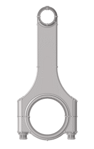
At first glance, the model might look perfect… but wait, don’t be so quick to judge!
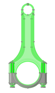
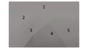
Switch the view to topology mode (in FEA, topology refers to the geometric definition and connectivity of features like lines, surfaces, and solids).
The bottom half remains gray, indicating an open-loop of surfaces that fail to form a solid. This could be due to data loss during import. Let’s rotate and zoom in to check further.
- Identifying Issues
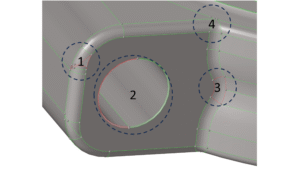
- First Mark – Missing and overlapping surfaces.
- Second Mark – Missing fillet surface.
- Third Mark – Unjoined edges of adjacent surfaces.
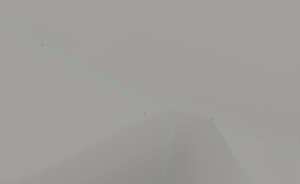
- Fourth Mark – Seems fine? Let’s zoom in and check again!
This is the worst nightmare for a mesh engineer. Elements in such complex regions will 100% fail in the quality check.
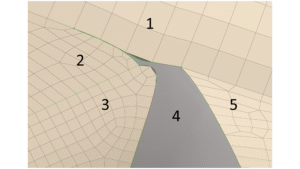
- The software fails to maintain element connectivity between Zone 1 and Zone 2.
- Zone 3 is difficult to maintain with a structured mesh.
- Zone 4 is impossible to mesh properly.
- Zone 5 contains sharp corners that degrade element quality.
- Even if Zone 4 is meshed, the elements will fail in simulation, reducing the stable time increment (discussed further in Step Time and Increment in Explicit Analysis blog).
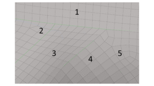
- Advanced Pre-processing Tools
With advanced pre-processing tools like HyperMesh and ANSA, these errors can be eliminated with just a few clicks! There is no need to wait for an updated design from the CAD engineer (who may not even fully understand the meshing requirements).
This is why, at ARSiTECH Enterprises, we say:
“Geometry cleanup and splitting is the ROADMAP for effective meshing.”
Proper pre-processing not only reduces meshing time but also improves simulation accuracy and decreases computational effort.
- Fixing Common Errors
To remove such errors, you can use:
- Toggle Edge – To adjust misaligned edges.
- Split Surface – To divide and refine surfaces.
- Suppress Edges – To remove unnecessary edges.
- Drag Surface – To create fillets where needed.
- Trim and Delete Extended Surfaces – To clean up excess geometry.
The following video will help you understand these techniques in detail.
To learn more about these commands, watch the detailed video linked below.
Video Placeholder: Link to tutorial